Stuart K. Scott, BASF-Color Science-Technical Advisor, BASF Corp., Southfield, MI11.06.17
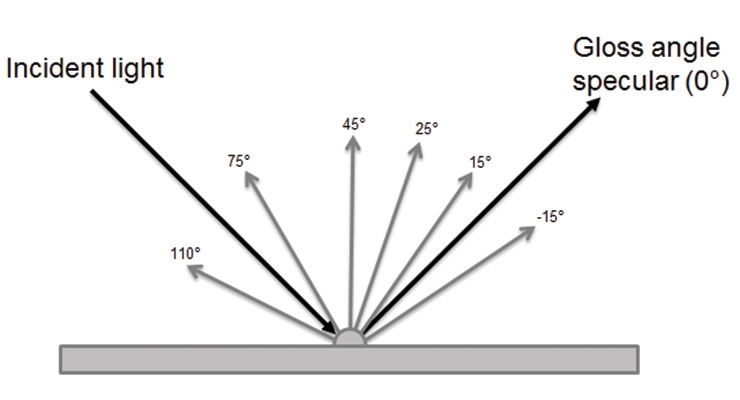
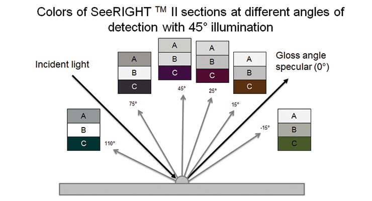
Automotive effect coatings usually contain flake pigments, which act somewhat like a mirror, causing the color to change based on the angle of illumination or view. Effect coatings are commonly measured for color using hand-held, multi-angle spectrophotometers with one angle of illumination (45o) and multiple angles of detection (-15, 15, 25, 45, 75, 110o) away from the specular reflection (Illustration 1). BYK-Gardner’s BYKmaci and X-Rite’s MA96 are examples of such instruments.
Correlating visual and instrumental assessment of color for effect coatings is notoriously difficult, because the viewing situation is often different from the measurement situation, and the differences can be quite complex.
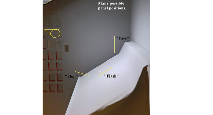
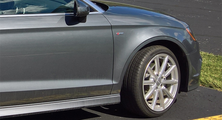
When panels are viewed in a light booth (Picture 1), the panels are moved to look at them at different viewing geometries. When automobiles are viewed in a booth or outside in the sun (Picture 2), observers move around the vehicle. As a result, both the angle of light incidence and the angle of detection change simultaneously.
This is completely unlike the spectrophotometer, where the angle of illumination is static. This geometric difference between the instrument and the visual setting sometimes results in discrepancies between visual observations and measurement interpretations. How can a technician understand and explain the reasons for such discrepancies? What is a technician to do in this difficult process of correlating visual and instrumental assessments?
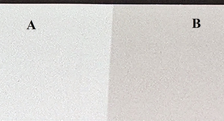
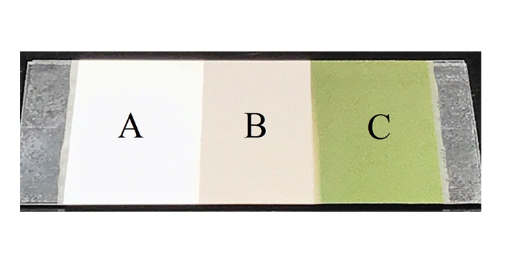
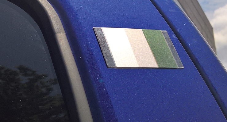
To help with correlating visual and instrumental results, BASF created a simple device called SeeRIGHT™ (Picture 3) that is painted with two coatings side-by-side.The first coating (A) contains only aluminum flake pigment, the second coating (B) contains aluminum flake plus white pigment. A further development of the device, SeeRIGHT™ II (Picture 4), possesses a third coating (C), which contains black pigment plus a high hue-shifting mica flake pigment. Simplistically, the aluminum flake scatters light in a highly-directional, mirror-like way; white pigment scatters light diffusely in all directions; and the colored mica changes hue based on the path length of light through the flake, which depends on both the angle of illumination and detection. Either device can be attached to a panel or automobile surface through various means, but in the simplest configuration the coatings are applied to a magnet which adheres to steel substrates.
Illustration 2 depicts how the SeeRIGHT™ II device looks when viewed in a booth that imitates precisely the most common multi-angle spectrophotometer configuration.
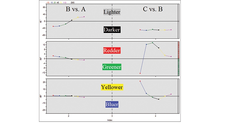
When coatings A, B, and C are measured with the multi-angle spectrophotometer, the multi-angle color difference can be plotted for B vs. A and C vs. B (Graph 1).
The measurements show that for near specular flash angles (-15, 15, 25 o) coating B is darker than A, and for far away from specular flop angles (75 and 110 o),
coating B is lighter than A. The measurements also show that coating C is darker at all angles relative to B, intensely greenish-yellow at the -15 o, intensely reddish-yellow at the 15 o, reddish at the 25 o, reddish-blue or purple at the 45 o, and not very colorful, essentially just dark, at the 75 and 110 o.
What then does this mean to the technician when he or she places the device onto a panel or a car that is being evaluated for color?
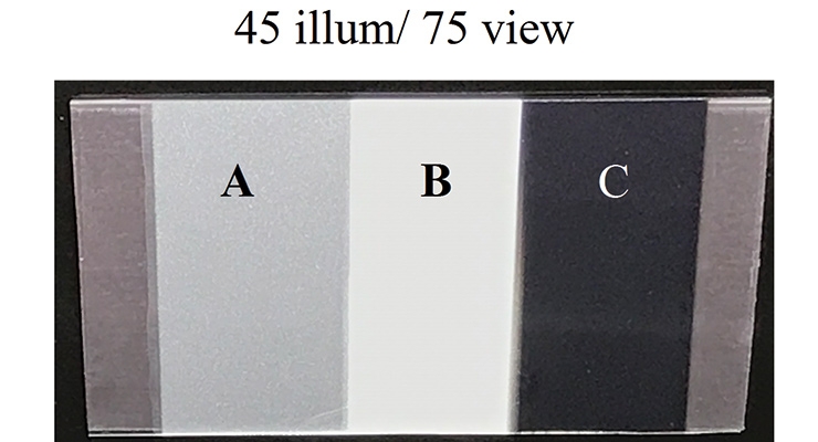
1. If coating B is lighter than the coating A, the viewing situation best correlates to the flop or the 75 and 110 o readings from the instrument (Picture 5).
2. If coating B is darker than coating A, the viewing situation best correlates to the flash or the -15, 15, or 25o readings from the instrument (Pictures 6, 7, 8).
Once it is determined that the viewing angle is the flash or near specular, the technician can use the color of coating C to verify whether the angle of illumination for that angle of view is the same as the spectrophotometer.
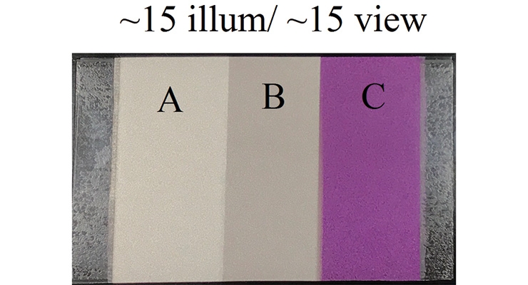
3. If coating B is darker than A, and coating C looks intense purple (Picture 6), then the angle of incidence is much steeper than what is normally measured, perhaps 15o illumination instead of the traditional 45o illumination.
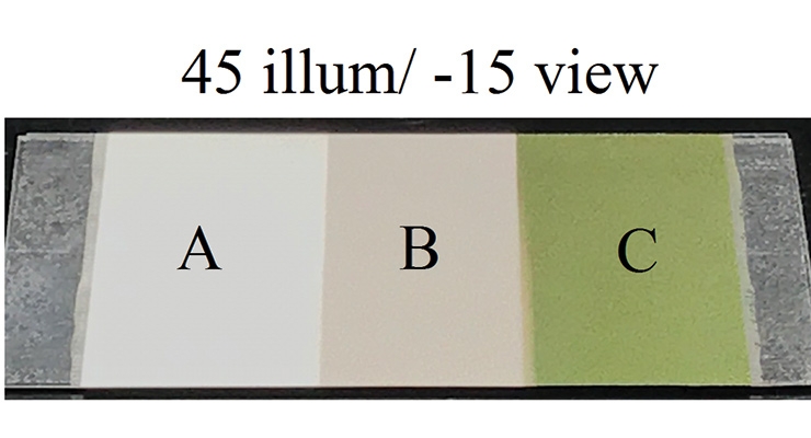
4. If coating B is darker than A, and coating C looks intense greenish-yellow (Pictures 7 and 8) or reddish-gold, this correlates to 45o illumination and -15 or 15o away from specular viewing, which is closest to the geometry of commonly used multi-angle spectrophotometers.
Armed with the SeeRIGHT™ II device and an understanding of why these coatings change colors as they do under different illumination/viewing conditions, the technician is better equipped to find the angles of view that correlate best with color measurements and explain any discrepancies that arise between visual and instrumental assessment of effect colors.
Scott is the technical advisor for BASF OEM Coatings in North America. He is an industry expert in the field of color science, serves as the lead on BASF’s Color Review Board and is the North American technical expert supporting BASF’s ColorCARE software.

